Saturday, 18 May 2019

What is Back EMF in a DC Motor?


When the DC voltage is applied to the armature, the voltage is produced across the armature winding which oppose the flow of armature current. The voltage produced across the armature is known as counter or back EMF.

The back EMF in the DC motor is expressed by the following mathematical expression.

Eb= ΦNZ/60 *P/A
Where,
Φ= Flux /Pole
N = Armature Speed
Z = Total number of armature conductor
A = Number of parallel paths in the armature winding

The back EMF is proportional to the speed of the motor.The back EMF governs the armature current and thus the back EMF maintains the speed and torque of the motor. The back EMF regulates the armature current and hence maintains the torque delivery to the load.

Ia=(V-Eb)/Ra

If the motor is loaded the speed get reduced. The reduction in the speed cause reduction in back EMF and the reduced EMF allow the motor to draw the more armature current and as a result the torque delivery of the motor(T= ΦIa)increase to meet the torque requirement of the load. When the load torque and the motor delivery torque requirement is meet the armature current gets reduced.
If the load is thrown off the speed of the motor gets increased and the motor torque is now much more than the load torque. With an increase in the speed the back EMF gets increased and the armature current gets reduced. The torque delivering of the motor automatically reduces.
Thus the back EMF maintains the armature current to deliver the torque as per the load requirement
What does 5P10 & 5P20 mean for CT?

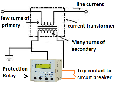
Protection of the electrical network is paramount for ensuring the isolation of the faulty section in order to maintain uninterrupted power supply to other healthy electrical netwoks. The protection relay and the current transformer which measures the current and fed that current to the protection relay must be most reliable. The careful selection of the protection class CT is most important parameter to ensure no CT saturation at the time of fault. The protection class CT has more knee point saturation point as compared to metering class CT.
Protection class (P class) CT is connected to the protection relay that gives tripping command to circuit breaker at the time of fault condition. The protection scheme of feeder as given below.
At the time of the fault, the primary current of CT increases abnormally high and the core can get magnetized above its rated capacity and whatever fault current flowing in the circuit can’t be reflected in the secondary side of the CT. This phenomenon is known as the saturation of CT. If CT gets saturated at the time of the fault, the protection relay will not operate.
5P10 class CT: 
P stands for protection class. If the primary current is 10 times to the rated primary current of the CT, the CT will function perfectly, within the rated composite accuracy class 5 %.
5P20 class CT: 
P stands for protection class. If the primary current is 20 times to the rated primary current of the CT, the CT will function perfectly, within the rated composite accuracy class 5 %.

A CTR of 200/5 with 5P10 class will give error of 5 % if the primary current through the CT is 2000 ampere.

A CTR of 200/5 with 5P20 class will give error of 5 % if the primary current through the CT is 4000 ampere.


Sunday, 6 January 2019

The Reasons Of Keeping V/f Ratio Constant in VFD

Speed Control of Induction Motor


The speed of the induction motor can be controlled by varying the voltage, frequency, number of poles and by changing the slip by adding external resistance to the rotor winding. The speed of the motor can be expressed by the following mathematical formula.

N=120f/P(1-s)

Where f- frequency, P= No. of Poles and s is the slip of the motor.

First, let us understand what is the significance of the V/f ratio in an induction motor. When the sinusoidal voltage is applied to the stator of the induction motor, the current starts flowing in the winding and the current induces the voltage of opposite polarity to the applied voltage. The magnitude of the induced voltage across the stator (Eb) depends on the frequency and voltage of the applied voltage(Vry).

The magnitude of the induced voltage can be expressed by the following mathematical expression;
In simple expression, the induced EMF across stator is as given below.

Eb=4.44∗Flux∗Frequency∗Number of Turns/phase
Eb=4.44FluxFrequencyNumbeoTurns/phase

Flux= K* (Eb/ f)---------------(1)
Where, K- Constant, Eb- Induced EMF in the stator winding, f- frequency of the stator voltage
From above equation (1) it is clear that the flux in the air gap can be kept constant if the V/f ratio is kept constant.
The VF drive is very popular nowadays because of ease of the speed control. The speed of the induction motor is varied by changing the frequency reference set point of the drive. The frequency is increased if speed is required to be increased. The pulse width modulator (PWM) of the drive takes action to increase or decrease the voltage proportionately with an increase/decrease in the frequency.
                             PWM Inverter Waveform
Even though the variation in the voltage with the variation in the frequency does not contribute to the speed variation of the motor, the variation in voltage is just done to keep the flux constant. 
This way the drive maintains the constant flux in the air gap of the motor.
The adverse effect of Over fluxing/under fluxing of the motor are as follows.
The flux in the core depends on the ratio of voltage and frequency. If the V/f ratio is not maintained the flux in the core would increase/decrease. With increased flux density above the rated core flux density, the temperature of the core will increase, and because of increased core temperature, the motor winding insulation may break down. The application in which high starting torque is required can be met by keeping the V/F ratio higher than the rated flux of the motor during acceleration of the motor. This feature is known as the “ starting torque Boosting” of the drive. The drive maintains the v/f ratio constant after accelerating to the rated speed, and the drive delivers constant torque. This feature can be used for starting high inertia loads like Rotary Kiln, Bucket elevators, belt conveyors, etc.

If the motor is operated at decreased flux density, the torque-delivering capacity of the motor would get decreased, and at full load, the motor may trip with overload. In an application where the running torque requirement is low, the V/f ratio can be reduced from its rated value to minimize the iron losses in the motor.


What is the Single Phase Motor Humming Problem?

Single Phase Motor Humming Problem is the alternating magnetic field trying to move the rotor in both directions at the same time.  Reason ...