Saturday, 18 May 2019

What is Back EMF in a DC Motor?


When the DC voltage is applied to the armature, the voltage is produced across the armature winding which oppose the flow of armature current. The voltage produced across the armature is known as counter or back EMF.

The back EMF in the DC motor is expressed by the following mathematical expression.

Eb= ΦNZ/60 *P/A
Where,
Φ= Flux /Pole
N = Armature Speed
Z = Total number of armature conductor
A = Number of parallel paths in the armature winding

The back EMF is proportional to the speed of the motor.The back EMF governs the armature current and thus the back EMF maintains the speed and torque of the motor. The back EMF regulates the armature current and hence maintains the torque delivery to the load.

Ia=(V-Eb)/Ra

If the motor is loaded the speed get reduced. The reduction in the speed cause reduction in back EMF and the reduced EMF allow the motor to draw the more armature current and as a result the torque delivery of the motor(T= ΦIa)increase to meet the torque requirement of the load. When the load torque and the motor delivery torque requirement is meet the armature current gets reduced.
If the load is thrown off the speed of the motor gets increased and the motor torque is now much more than the load torque. With an increase in the speed the back EMF gets increased and the armature current gets reduced. The torque delivering of the motor automatically reduces.
Thus the back EMF maintains the armature current to deliver the torque as per the load requirement
What does 5P10 & 5P20 mean for CT?

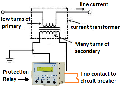
Protection of the electrical network is paramount for ensuring the isolation of the faulty section in order to maintain uninterrupted power supply to other healthy electrical netwoks. The protection relay and the current transformer which measures the current and fed that current to the protection relay must be most reliable. The careful selection of the protection class CT is most important parameter to ensure no CT saturation at the time of fault. The protection class CT has more knee point saturation point as compared to metering class CT.
Protection class (P class) CT is connected to the protection relay that gives tripping command to circuit breaker at the time of fault condition. The protection scheme of feeder as given below.
At the time of the fault, the primary current of CT increases abnormally high and the core can get magnetized above its rated capacity and whatever fault current flowing in the circuit can’t be reflected in the secondary side of the CT. This phenomenon is known as the saturation of CT. If CT gets saturated at the time of the fault, the protection relay will not operate.
5P10 class CT: 
P stands for protection class. If the primary current is 10 times to the rated primary current of the CT, the CT will function perfectly, within the rated composite accuracy class 5 %.
5P20 class CT: 
P stands for protection class. If the primary current is 20 times to the rated primary current of the CT, the CT will function perfectly, within the rated composite accuracy class 5 %.

A CTR of 200/5 with 5P10 class will give error of 5 % if the primary current through the CT is 2000 ampere.

A CTR of 200/5 with 5P20 class will give error of 5 % if the primary current through the CT is 4000 ampere.


What is the Single Phase Motor Humming Problem?

Single Phase Motor Humming Problem is the alternating magnetic field trying to move the rotor in both directions at the same time.  Reason ...