Tuesday, 29 December 2020

What is DC Machine?

DC Machine

A DC Machine converts electrical energy into mechanical energy or mechanical energy into electrical energy.  The DC motor converts electrical energy into mechanical energy , and the DC generator converts mechanical energy into electrical energy.

DC  motor is widely used in the industrial applications where high starting torque and good speed regulation is desired. The DC motor has better speed regulation and high starting torque in comparison with the AC motor.

The construction of the DC motor and generator is almost similar. The generator is generally housed in the closed room and generator may be of open construction type. However, the DC motor is used at the site in the plant which may have dust and heat. Therefore, the DC motor enclosure is  dust proof , fire proof, as per the applications.

The DC generator is used for the application where large DC power is required. The applications are electrolysis, electroplating etc.

Construction of Electrical DC Machines

The DC motor and DC generator have mainly two parts; stator and rotor. In dc motor stator is the stationary part and the rotor is rotating part. The rotor rotates in the air gap.The field winding is housed in the stator slots. The field winding produces the required magnetic field for motor operation. The armature winding is housed in the rotor. When DC voltage is fed to armature winding under magnetic field produced by field winding induce the voltage in the armature winding.

The small rating DC generator has field winding or permanent magnet on stationary part and voltage is taken out from the rotating part. In a large rating DC generator the field coils are housed on the rotor and the armature winding is housed in the stator part.

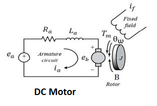
Equivalent Circuit of a DC Machines 

The equivalent circuit of the DC generator can be represented by three series-connected elements E, Ra and Vb.

The equivalent circuit of the DC motor  is as given below.
Where,
Ra = Armature Resistance
eb  = Back EMF
V = Applied voltage ( In case of DC Motor)
     = Generated voltage in case of DC generator 


Tuesday, 8 December 2020

Use of Line or Phase Tester

Construction and Working of Line Tester

For maintenance, troubleshooting, and checking of electrical equipment phase tester is used to detect whether the particular point has live potential or not. Thus the line tester is used to detect the voltage. The line tester does not measure the voltage, it only shows whether voltage exists at a particular point or not. The line tester never detects the current in the circuit.


Parts of Line Tester


1). Metallic Rod and Mouth

The metallic rod is of cylindrical type and its flat part is covered with insulation. The farthest part of the rod is conductive and it makes the connection with the live part. The other end of the metallic rod is connected with the current limiting resistor, neon bulb, element, and metallic cap screw respectively. It is a cylindrical metal rod. 

2). Body and Insulation

All the components Resistance, Neon bulb, Element or metallic spring, and Metallic Cap screw are housed in the enclosure which is covered in a transparent insulated body. 

3). Resistor

The resistor is used to limit the current flowing in the circuit. The resistance is connected between the cylindrical rod and the neon element. The current flowing through the live conductor to the earth when the end of the tester body is touched depends on the value of the resistance. The resistance value is selected in such a way that the current flowing through the human body to earth is in order of safe limit. 

4). Neon Bulb

The neon bulb is connected between resistance and metallic spring. When a small current flows through the resistor it starts glowing which indicates that the measuring point has live potential. It is used as a phase indicator bulb. 

5). Element (Metallic Spring)

The neon bulb and metallic cap screw are connected through the metallic spring.

6). Metallic Cap Screw and Clip

The metallic cap screw is connected with the spring and the spring element is connected with the neon bulb. The metallic cap screw is used to tighten all the components inside the tester. The clip attached to it is useful for clipping the tester inside the pocket.

Working Principle of Line Tester

When we touch the flat end of the metallic rod of phase or line tester with naked Live/hot wire then the circuit gets completed and current starts flowing in metallic rod, and the neon bulb inside mains tester glows. The glowing of the neon bulb shows that there is a supply in the wire. If a neon bulb does not flow indicates that there is no supply in the phase wire.

To limit the current flowing through the neon bulb current limiting resistor is connected in the series of the neon bulb. The metallic spring is connected with a metallic cap screw which is in contact with our fingers. Thus, a very small current flows through our body to the earth and completes the circuit. 

Precaution while working 

One must concentrate on the measuring point where the line tester tip is put for detecting the voltage. The slippage of the tester tip may lead to phase to earth short circuit and can cause accidents.

Reference:

Electrical line Tester- Its Construction & Working


What is the Single Phase Motor Humming Problem?

Single Phase Motor Humming Problem is the alternating magnetic field trying to move the rotor in both directions at the same time.  Reason ...