Saturday, 27 November 2021

What happens if we increase or decrease running winding turns of a single phase induction motor?

If we increase turns

Idle current and HP will decrease in proportions to the square of the change in turns. Locked rotor current and starting torque will decrease in direct proportion to the change in turns.

If we decrease turns

Idle current and HP will increase in proportion to the square of the change in turns, Locked rotor current and starting torque will also increase in direct proportion to the change in turns.

Decreasing in turns leads to core saturation. For example, a 5hp motor, and that core (rotor and stator), are not going to do well if you try to make it a 10hp motor.

We can’t decrease turns much unless you want to make a hot motor with say a 10-minute duty cycle (10 minutes per hour).

If we have capacity margin in motor

If you had a motor made before 1950 you could probably increase the HP by 25% because they had large frames, low flux density, and low design temperature.

Your starting and accelerating torque will drop a little unless you change the start winding too.

Saturday, 9 January 2021

Why are circular coils preferred in transformers?

The circular coils in the transformer have the following advantages over rectangular form coils.


  • The circular coil has a minimum mean length of the turn. If the diameter of the circular coil is d, the length of one turn πd. The length of the one turn of the rectangular coil is 2d. Thus, the circular coils have about 1/3 rd length in comparison with rectangular coils. The less length of the wire means the less ohmic value because the resistance of the wire is directly proportional to its length. The heat loss in the case of the circular coil is minimum.
  • Under fault conditions, the coils of the transformer experienced heavy electromagnetic forces. The force act on the central axis of the coil. In a circular coil, the force is even throughout the coil, whereas the force on the rectangular coil is uneven and the force is maximum at the center and weaker at the edges of the coil. Thus, the rectangular coils are prone to damage under fault conditions.
  • The winding of the circular coil is easy to form. There is a chance of insulation damage at the corners of the rectangular coils.


Related Post:

Why is the core of power transformer grounded?


Friday, 1 January 2021

What is PS Class CT?

Protection special class CT  'PS" or 'PX' is used for protection of the electrical equipment like motor, transformer, generator, and bus bar. The protection or P class current transformer is used for the protection of feeders. 

The central theme of any electrical protection scheme is that the current should not saturate at the time when fault current flows through the current transformer. Under CT saturation conditions, it behaves as an open circuit, and protection of the electrical equipment is not guaranteed. 

The protection class or 'P' class CT like 5P10, 5P20 is used for the protection of feeders. The knee point voltage of protection class CT  is more than the knee point voltage of the metering class CT. It means the protection class CT saturates at much higher CT secondary voltage.

For the protection of the alternator, generator, high tension motor and bus bar, protection zone, differential protection, or unit protection scheme is used. The unit protection scheme provides tripping to the breaker in case there is a fault within the equipment. For instance, the differential protection trip in the transformer feeder shows that there is a fault in the transformer. If the differential protection relay operates, it is essential to check the transformer before switching on the equipment again.

The differential protection scheme is designed by selecting the PS class CT. The PS class CT has a higher knee point voltage. The following parameters of the current transformer of CT used for the PS class must be defined.

  • Knee Point Voltage Vk(KPV) Minimum - Volts
  • Excitation Current(Maximum) at Vk/2 - Amperes
  • Rct (secondary winding resistance) at 75 Degree Centigrade (In Ohm)
Specifications of the PS class CT are as given below.

The PS class CT used for the differential transformer must have identical magnetization characteristics. Any Aberration in the CT characteristics used on the primary and secondary side may lead to spurious tripping during the through fault condition.


Tuesday, 29 December 2020

What is DC Machine?

DC Machine

A DC Machine converts electrical energy into mechanical energy or mechanical energy into electrical energy.  The DC motor converts electrical energy into mechanical energy , and the DC generator converts mechanical energy into electrical energy.

DC  motor is widely used in the industrial applications where high starting torque and good speed regulation is desired. The DC motor has better speed regulation and high starting torque in comparison with the AC motor.

The construction of the DC motor and generator is almost similar. The generator is generally housed in the closed room and generator may be of open construction type. However, the DC motor is used at the site in the plant which may have dust and heat. Therefore, the DC motor enclosure is  dust proof , fire proof, as per the applications.

The DC generator is used for the application where large DC power is required. The applications are electrolysis, electroplating etc.

Construction of Electrical DC Machines

The DC motor and DC generator have mainly two parts; stator and rotor. In dc motor stator is the stationary part and the rotor is rotating part. The rotor rotates in the air gap.The field winding is housed in the stator slots. The field winding produces the required magnetic field for motor operation. The armature winding is housed in the rotor. When DC voltage is fed to armature winding under magnetic field produced by field winding induce the voltage in the armature winding.

The small rating DC generator has field winding or permanent magnet on stationary part and voltage is taken out from the rotating part. In a large rating DC generator the field coils are housed on the rotor and the armature winding is housed in the stator part.

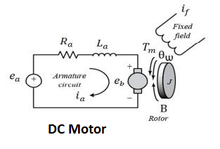
Equivalent Circuit of a DC Machines 

The equivalent circuit of the DC generator can be represented by three series-connected elements E, Ra and Vb.

The equivalent circuit of the DC motor  is as given below.
Where,
Ra = Armature Resistance
eb  = Back EMF
V = Applied voltage ( In case of DC Motor)
     = Generated voltage in case of DC generator 


Tuesday, 8 December 2020

Use of Line or Phase Tester

Construction and Working of Line Tester

For maintenance, troubleshooting, and checking of electrical equipment phase tester is used to detect whether the particular point has live potential or not. Thus the line tester is used to detect the voltage. The line tester does not measure the voltage, it only shows whether voltage exists at a particular point or not. The line tester never detects the current in the circuit.


Parts of Line Tester


1). Metallic Rod and Mouth

The metallic rod is of cylindrical type and its flat part is covered with insulation. The farthest part of the rod is conductive and it makes the connection with the live part. The other end of the metallic rod is connected with the current limiting resistor, neon bulb, element, and metallic cap screw respectively. It is a cylindrical metal rod. 

2). Body and Insulation

All the components Resistance, Neon bulb, Element or metallic spring, and Metallic Cap screw are housed in the enclosure which is covered in a transparent insulated body. 

3). Resistor

The resistor is used to limit the current flowing in the circuit. The resistance is connected between the cylindrical rod and the neon element. The current flowing through the live conductor to the earth when the end of the tester body is touched depends on the value of the resistance. The resistance value is selected in such a way that the current flowing through the human body to earth is in order of safe limit. 

4). Neon Bulb

The neon bulb is connected between resistance and metallic spring. When a small current flows through the resistor it starts glowing which indicates that the measuring point has live potential. It is used as a phase indicator bulb. 

5). Element (Metallic Spring)

The neon bulb and metallic cap screw are connected through the metallic spring.

6). Metallic Cap Screw and Clip

The metallic cap screw is connected with the spring and the spring element is connected with the neon bulb. The metallic cap screw is used to tighten all the components inside the tester. The clip attached to it is useful for clipping the tester inside the pocket.

Working Principle of Line Tester

When we touch the flat end of the metallic rod of phase or line tester with naked Live/hot wire then the circuit gets completed and current starts flowing in metallic rod, and the neon bulb inside mains tester glows. The glowing of the neon bulb shows that there is a supply in the wire. If a neon bulb does not flow indicates that there is no supply in the phase wire.

To limit the current flowing through the neon bulb current limiting resistor is connected in the series of the neon bulb. The metallic spring is connected with a metallic cap screw which is in contact with our fingers. Thus, a very small current flows through our body to the earth and completes the circuit. 

Precaution while working 

One must concentrate on the measuring point where the line tester tip is put for detecting the voltage. The slippage of the tester tip may lead to phase to earth short circuit and can cause accidents.

Reference:

Electrical line Tester- Its Construction & Working


Saturday, 18 May 2019

What is Back EMF in a DC Motor?


When the DC voltage is applied to the armature, the voltage is produced across the armature winding which oppose the flow of armature current. The voltage produced across the armature is known as counter or back EMF.

The back EMF in the DC motor is expressed by the following mathematical expression.

Eb= ΦNZ/60 *P/A
Where,
Φ= Flux /Pole
N = Armature Speed
Z = Total number of armature conductor
A = Number of parallel paths in the armature winding

The back EMF is proportional to the speed of the motor.The back EMF governs the armature current and thus the back EMF maintains the speed and torque of the motor. The back EMF regulates the armature current and hence maintains the torque delivery to the load.

Ia=(V-Eb)/Ra

If the motor is loaded the speed get reduced. The reduction in the speed cause reduction in back EMF and the reduced EMF allow the motor to draw the more armature current and as a result the torque delivery of the motor(T= ΦIa)increase to meet the torque requirement of the load. When the load torque and the motor delivery torque requirement is meet the armature current gets reduced.
If the load is thrown off the speed of the motor gets increased and the motor torque is now much more than the load torque. With an increase in the speed the back EMF gets increased and the armature current gets reduced. The torque delivering of the motor automatically reduces.
Thus the back EMF maintains the armature current to deliver the torque as per the load requirement

What does 5P10 & 5P20 mean for CT?

Protection of the electrical network is paramount for ensuring the isolation of the faulty section in order to maintain uninterrupted power supply to other healthy electrical netwoks. The protection relay and the current transformer which measures the current and fed that current to the protection relay must be most reliable. The careful selection of the protection class CT is most important parameter to ensure no CT saturation at the time of fault. The protection class CT has more knee point saturation point as compared to metering class CT.
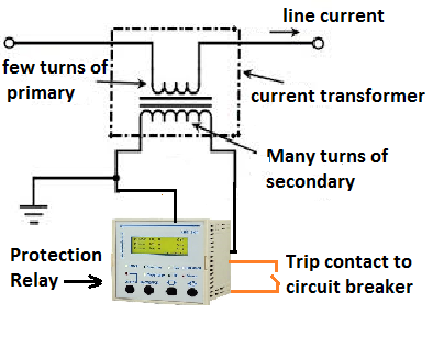
Protection class (P class) CT is connected to the protection relay that gives tripping command to circuit breaker at the time of fault condition. The protection scheme of feeder as given below.
At the time of the fault, the primary current of CT increases abnormally high and the core can get magnetized above its rated capacity and whatever fault current flowing in the circuit can’t be reflected in the secondary side of the CT. This phenomenon is known as the saturation of CT. If CT gets saturated at the time of the fault, the protection relay will not operate.
5P10 class CT: 
P stands for protection class. If the primary current is 10 times to the rated primary current of the CT, the CT will function perfectly, within the rated composite accuracy class 5 %.
5P20 class CT: 
P stands for protection class. If the primary current is 20 times to the rated primary current of the CT, the CT will function perfectly, within the rated composite accuracy class 5 %.

A CTR of 200/5 with 5P10 class will give error of 5 % if the primary current through the CT is 2000 ampere.

A CTR of 200/5 with 5P20 class will give error of 5 % if the primary current through the CT is 4000 ampere.


What is the Single Phase Motor Humming Problem?

Single Phase Motor Humming Problem is the alternating magnetic field trying to move the rotor in both directions at the same time.  Reason ...