Tuesday, 29 December 2020

What is DC Machine?

DC Machine

A DC Machine converts electrical energy into mechanical energy or mechanical energy into electrical energy.  The DC motor converts electrical energy into mechanical energy , and the DC generator converts mechanical energy into electrical energy.

DC  motor is widely used in the industrial applications where high starting torque and good speed regulation is desired. The DC motor has better speed regulation and high starting torque in comparison with the AC motor.

The construction of the DC motor and generator is almost similar. The generator is generally housed in the closed room and generator may be of open construction type. However, the DC motor is used at the site in the plant which may have dust and heat. Therefore, the DC motor enclosure is  dust proof , fire proof, as per the applications.

The DC generator is used for the application where large DC power is required. The applications are electrolysis, electroplating etc.

Construction of Electrical DC Machines

The DC motor and DC generator have mainly two parts; stator and rotor. In dc motor stator is the stationary part and the rotor is rotating part. The rotor rotates in the air gap.The field winding is housed in the stator slots. The field winding produces the required magnetic field for motor operation. The armature winding is housed in the rotor. When DC voltage is fed to armature winding under magnetic field produced by field winding induce the voltage in the armature winding.

The small rating DC generator has field winding or permanent magnet on stationary part and voltage is taken out from the rotating part. In a large rating DC generator the field coils are housed on the rotor and the armature winding is housed in the stator part.

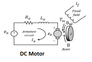
Equivalent Circuit of a DC Machines 

The equivalent circuit of the DC generator can be represented by three series-connected elements E, Ra and Vb.

The equivalent circuit of the DC motor  is as given below.
Where,
Ra = Armature Resistance
eb  = Back EMF
V = Applied voltage ( In case of DC Motor)
     = Generated voltage in case of DC generator 


Tuesday, 8 December 2020

Use of Line or Phase Tester

Construction and Working of Line Tester

For maintenance, troubleshooting, and checking of electrical equipment phase tester is used to detect whether the particular point has live potential or not. Thus the line tester is used to detect the voltage. The line tester does not measure the voltage, it only shows whether voltage exists at a particular point or not. The line tester never detects the current in the circuit.


Parts of Line Tester


1). Metallic Rod and Mouth

The metallic rod is of cylindrical type and its flat part is covered with insulation. The farthest part of the rod is conductive and it makes the connection with the live part. The other end of the metallic rod is connected with the current limiting resistor, neon bulb, element, and metallic cap screw respectively. It is a cylindrical metal rod. 

2). Body and Insulation

All the components Resistance, Neon bulb, Element or metallic spring, and Metallic Cap screw are housed in the enclosure which is covered in a transparent insulated body. 

3). Resistor

The resistor is used to limit the current flowing in the circuit. The resistance is connected between the cylindrical rod and the neon element. The current flowing through the live conductor to the earth when the end of the tester body is touched depends on the value of the resistance. The resistance value is selected in such a way that the current flowing through the human body to earth is in order of safe limit. 

4). Neon Bulb

The neon bulb is connected between resistance and metallic spring. When a small current flows through the resistor it starts glowing which indicates that the measuring point has live potential. It is used as a phase indicator bulb. 

5). Element (Metallic Spring)

The neon bulb and metallic cap screw are connected through the metallic spring.

6). Metallic Cap Screw and Clip

The metallic cap screw is connected with the spring and the spring element is connected with the neon bulb. The metallic cap screw is used to tighten all the components inside the tester. The clip attached to it is useful for clipping the tester inside the pocket.

Working Principle of Line Tester

When we touch the flat end of the metallic rod of phase or line tester with naked Live/hot wire then the circuit gets completed and current starts flowing in metallic rod, and the neon bulb inside mains tester glows. The glowing of the neon bulb shows that there is a supply in the wire. If a neon bulb does not flow indicates that there is no supply in the phase wire.

To limit the current flowing through the neon bulb current limiting resistor is connected in the series of the neon bulb. The metallic spring is connected with a metallic cap screw which is in contact with our fingers. Thus, a very small current flows through our body to the earth and completes the circuit. 

Precaution while working 

One must concentrate on the measuring point where the line tester tip is put for detecting the voltage. The slippage of the tester tip may lead to phase to earth short circuit and can cause accidents.

Reference:

Electrical line Tester- Its Construction & Working


Saturday, 18 May 2019

What is Back EMF in a DC Motor?


When the DC voltage is applied to the armature, the voltage is produced across the armature winding which oppose the flow of armature current. The voltage produced across the armature is known as counter or back EMF.

The back EMF in the DC motor is expressed by the following mathematical expression.

Eb= ΦNZ/60 *P/A
Where,
Φ= Flux /Pole
N = Armature Speed
Z = Total number of armature conductor
A = Number of parallel paths in the armature winding

The back EMF is proportional to the speed of the motor.The back EMF governs the armature current and thus the back EMF maintains the speed and torque of the motor. The back EMF regulates the armature current and hence maintains the torque delivery to the load.

Ia=(V-Eb)/Ra

If the motor is loaded the speed get reduced. The reduction in the speed cause reduction in back EMF and the reduced EMF allow the motor to draw the more armature current and as a result the torque delivery of the motor(T= ΦIa)increase to meet the torque requirement of the load. When the load torque and the motor delivery torque requirement is meet the armature current gets reduced.
If the load is thrown off the speed of the motor gets increased and the motor torque is now much more than the load torque. With an increase in the speed the back EMF gets increased and the armature current gets reduced. The torque delivering of the motor automatically reduces.
Thus the back EMF maintains the armature current to deliver the torque as per the load requirement

What does 5P10 & 5P20 mean for CT?

Protection of the electrical network is paramount for ensuring the isolation of the faulty section in order to maintain uninterrupted power supply to other healthy electrical netwoks. The protection relay and the current transformer which measures the current and fed that current to the protection relay must be most reliable. The careful selection of the protection class CT is most important parameter to ensure no CT saturation at the time of fault. The protection class CT has more knee point saturation point as compared to metering class CT.
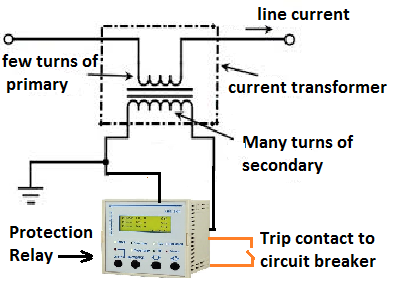
Protection class (P class) CT is connected to the protection relay that gives tripping command to circuit breaker at the time of fault condition. The protection scheme of feeder as given below.
At the time of the fault, the primary current of CT increases abnormally high and the core can get magnetized above its rated capacity and whatever fault current flowing in the circuit can’t be reflected in the secondary side of the CT. This phenomenon is known as the saturation of CT. If CT gets saturated at the time of the fault, the protection relay will not operate.
5P10 class CT: 
P stands for protection class. If the primary current is 10 times to the rated primary current of the CT, the CT will function perfectly, within the rated composite accuracy class 5 %.
5P20 class CT: 
P stands for protection class. If the primary current is 20 times to the rated primary current of the CT, the CT will function perfectly, within the rated composite accuracy class 5 %.

A CTR of 200/5 with 5P10 class will give error of 5 % if the primary current through the CT is 2000 ampere.

A CTR of 200/5 with 5P20 class will give error of 5 % if the primary current through the CT is 4000 ampere.


Sunday, 6 January 2019

The Reasons Of Keeping V/f Ratio Constant in VFD

Speed Control of Induction Motor


The speed of the induction motor can be controlled by varying the voltage, frequency, number of poles and by changing the slip by adding external resistance to the rotor winding. The speed of the motor can be expressed by the following mathematical formula.

N=120f/P(1-s)

Where f- frequency, P= No. of Poles and s is the slip of the motor.

First, let us understand what is the significance of the V/f ratio in an induction motor. When the sinusoidal voltage is applied to the stator of the induction motor, the current starts flowing in the winding and the current induces the voltage of opposite polarity to the applied voltage. The magnitude of the induced voltage across the stator (Eb) depends on the frequency and voltage of the applied voltage(Vry).

The magnitude of the induced voltage can be expressed by the following mathematical expression;
In simple expression, the induced EMF across stator is as given below.

Eb=4.44∗Flux∗Frequency∗Number of Turns/phase
Eb=4.44FluxFrequencyNumbeoTurns/phase

Flux= K* (Eb/ f)---------------(1)
Where, K- Constant, Eb- Induced EMF in the stator winding, f- frequency of the stator voltage
From above equation (1) it is clear that the flux in the air gap can be kept constant if the V/f ratio is kept constant.
The VF drive is very popular nowadays because of ease of the speed control. The speed of the induction motor is varied by changing the frequency reference set point of the drive. The frequency is increased if speed is required to be increased. The pulse width modulator (PWM) of the drive takes action to increase or decrease the voltage proportionately with an increase/decrease in the frequency.
                             PWM Inverter Waveform
Even though the variation in the voltage with the variation in the frequency does not contribute to the speed variation of the motor, the variation in voltage is just done to keep the flux constant. 
This way the drive maintains the constant flux in the air gap of the motor.
The adverse effect of Over fluxing/under fluxing of the motor are as follows.
The flux in the core depends on the ratio of voltage and frequency. If the V/f ratio is not maintained the flux in the core would increase/decrease. With increased flux density above the rated core flux density, the temperature of the core will increase, and because of increased core temperature, the motor winding insulation may break down. The application in which high starting torque is required can be met by keeping the V/F ratio higher than the rated flux of the motor during acceleration of the motor. This feature is known as the “ starting torque Boosting” of the drive. The drive maintains the v/f ratio constant after accelerating to the rated speed, and the drive delivers constant torque. This feature can be used for starting high inertia loads like Rotary Kiln, Bucket elevators, belt conveyors, etc.

If the motor is operated at decreased flux density, the torque-delivering capacity of the motor would get decreased, and at full load, the motor may trip with overload. In an application where the running torque requirement is low, the V/f ratio can be reduced from its rated value to minimize the iron losses in the motor.


What is the Single Phase Motor Humming Problem?

Single Phase Motor Humming Problem is the alternating magnetic field trying to move the rotor in both directions at the same time.  Reason ...